
| The CRYPT Mag |

So, just what is this collection of dirty, oily, clanky bits that some of us men (and a few ladies!) like talking about?
What are RPM, bhp, torque, and displacement?
Well, dear reader, bear with me for a while and I'll try and explain.
When the internal combustion engine was first used sucessfully, it's 'inventor' Etienne Lenoir, fed it on coal gas. The system did not compress the charge, so, although it was better than the alternative, which was steam, it wasn't that good!
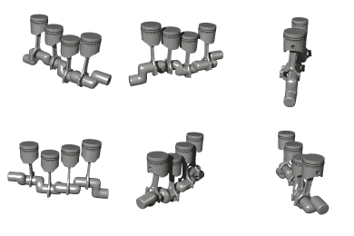
Enter a German named Dr N A Otto. He decided that the correct procedure for the use of a petrol-powered engine was to use a piston inside a gas-tight cylinder, that was able to slide up and down.

The top of the cylinder would have to have valves that would open and close on demand, within a strict regime. The earlier valves were simply holes in the cylinder bore, that would be uncovered at certain times as the piston moved up and down.
While this system worked quite well, it wasn't good enough, so Otto set about trying something new.
He eventually discovered that if he connected a crankshaft to the bottom end of the engine, and attached a rod to that and the bottom of the piston, attach a cog to the crankshaft, he could drive from the cog.
Next was to try and operate the valves. The valves were originally placed in the cylinder block beside the piston, and a thick flat plate (named the cylinder head) was bolted down to give the gas-tight seal.
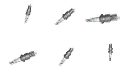
Underneath the valves was a second shaft, with lobes on it, which rotated at half the speed of the crankshaft. The lobes were adjusted in such a manner so as to force the valve to open upwards, and then its spring would force it back into place. In the centre of the head was a threaded hole so that a spark-plug was screwed in.

So, after some time, the theory was that the inlet valve opens, the piston would drop, sucking the air/fuel mixture into the top of the cylinder.
The inlet valve closes, the piston rises, compressing the charge, and at about the peak of its rise, (Top Dead-Centre, or TDC) the spark-plug delivers a healthy bolt of electricity, and the piston is forced back down.
As the piston reaches the bottom of its travel (Bottom Dead-Centre) the exhaust valve opens, and the burnt gasses are allowed to escape. Nowadays these gasses are channelled down the exhaust pipe.
As the piston approaches TDC, it starts again.
This Induction, Compression Power and Exhaust of the Otto-cycle is also known to us technical folk as Suck, Squeeze, Bang, Blow.
It was also necessary to add a weight to the end of the crankshaft to keep a one- or two- cylinder enging spinning.
As the engine would also need to speed up, a carburettor was added. This is an instrument that mixes air and petrol in a manner that the engine can use.
The principal parts of the carburettor are a venturi (a tube rather like a toilet roll tube nipped in the middle), a chamber to hold a small amount of petrol, and an emulsifying tube. The emulsifying tube is attached to the chamber, with the other end poking into the centre of the venturi.
The air that passes down the venturi, speeds up to get past the restriction, and in turn, draws some fuel from the float chamber. This mixture breaks the surface tension of the petrol, turning it into a vapour.
This vapour is drawn into the combustion chamber where it's used.
By increasing the air-flow, the engine can be made to spin faster.
This in turn made obvious the need for an advance/retard mechanism for the supply to the spark-plug(s).
As the engine spins faster, the spark needs to occur slightly sooner, so that everything else works on time.
The engine electrics are another consideration. There is a coil that generates a very high voltage, but it needs to be switched on and off. Inside the coil there are two circuits, one that simply allows voltage to pass through, the Low Tension (LT) circuit, and the High Tension circuit.
This switching, before transistorized ignition, was taken care of by a set of points and a condensor usually fitted inside the distributor.
Inside the distributor is a shaft driven at the same speed as the camshaft. The end of the shaft has a notch so that the rotor arm may by located correctly. The High Tension current is passed along the HT lead from the coil, down the centre of the distributor cap, where it's directed along the correct lead to the spark plug that needs to be fired.
Under the rotor arm, the shaft is shaped. If the engine is a four-cylinder model, there will be four lobes, 3 pots = 3 lobes, etc.
As the points close, the voltage across the points is directed into the condensor and the HT circuit is switched off. When the points open, the voltage is directed through the HT section of the coil, which produces the spark needed for combustion.
As the engine revs rise, there is a need for the spark to arrive a little earlier. The baseplate of the distributor is capable of rotating slightly, but is held in place by springs. Two small blocks, called bobweights are mounted on the driveshaft. These are attached loosely to the baseplate. The faster the shaft spins, the further the bobweights ar thrown outwards, and as they move out, they move the baseplate, thus advancing the ignition.
With the advent of electronic ignition, this function has largely been replaced by the electronic brain that is known as the ECU.
Some engine manufacturers have also taken the step of allowing the valve timing to be altered according to engine speed and load.

Karl Benz also had major input into the further development of the petrol engine, and when he teamed up with Gottlieb Daimler, they really took off! This partnership spawned the conglomerate that is known world-wide as Mercedes-Benz.
The only two real advances that have been made to this system is to allow different fuels to be used, Dr Rudolf Diesel invented the oil-burner that carries his name, and the somewhat unfortunately named Dr Felix Wankel also made a revolutionary discovery!
The major difference with the Diesel system is that spark-plugs are not employed, but as Diesel fuel doesn't emulsify the same as petrol does, it has to be squirted into the chamber using an injector.
Originally, Diesel injectors had a needle inside a shaped tube, which was held in place by a spring. The fuel oil is drawn from the fuel tank by a lift pump, and fed to the injector pump. The injector pump is responsible for the metering and distribution of the fuel.
As the fuel is fed pumped to the injector, the pressure forces the needle off it's seat, which then squirts down through the open end of the injector body. As spring pressure overcomes the fluid pressure, the needle re-seats.
This injection of fuel is timed to coincide with the descending piston. As it does so, the fluid is atomised and mixes with the air drawn into the compression chamber by the descending piston. At around BDC, the injector finishes injecting and the inlet valve closes.
As the piston rises and the charge is compressed, it becomes hotter. When it achieves a certain temperature, it will self-detonate. Thus the only way to stop a Diesel engine is to literally strangle it!
Diesel engines sometimes need a little help starting on cold days. This is when a Diesel pre-heater is really helpful! This simply warms the fuel up before it's needed.
Modern Diesels now only have one pump, and electronic injectors.
The fuel line is kept under constant high pressure, and the injectors are fired by the ECU. They can also be altered for duration (the amount of time the injector is open) and quantity. This will allow for a range of variables, from pulling a load uphill to coasting down the other side.
Dr Felix Wankel discovered that if a triangular rotor revolves about a central cogged shaft, inside an epitrochoid (look it up, I did!), it drives the central shaft.
The flat faces in the sides of the rotor have depressions that can be used in almost exactly the same manner as the combustion chamber on a piston-engine.
As the rotor passes certain parts of the inside of the bore, it uncovers ports which allow fresh charge in, and exhaust gasses out.
Although the layout is vastly different, the Suck, Squeeze, Bang, Blow principle still holds true.
Many other peripherals have been added to engines over the years; superchargers, turbochargers, fuel injection, to name but three.
Whilst these have altered the characteristics of the engine, they haven't changed to basic principles.
The supercharger is basically a mechanical pump that forces air into the carburettor, and the turbocharger is an exhaust-driven pump that does the same job.
An intercooler simply cools the air down, as cool air is more dense than warm air. This is why your freezer sometimes whistles after you've shut the door.
It also explains why engines seem more efficient in winter!
But what do those RPM, bhp, torque, and displacement things actually mean?
BHP is Brake Horse Power. This is a measure of how much power an engine can supply.
RPM, Revolutions Per Minute, is the number of complete turns of the crankshaft occur in a sixty-second interval.
Torque is the amount of twist an engine can supply.
Displacement is the size of the engine measured in terms of either cc's or litres.
Bore is the diameter of the cylinder.
Stroke is the amount that the piston moves up and down.
Compression Ratio is the amount of space in the bore at Bottom Dead Centre, and compressed into the space when the piston reaches Top Dead Centre. Thus, if the stroke is 90 mm and leaves a space of 10mm clearance at TDC the Compression Ratio would be 9:1.

| © RIYAN Productions |
