|
|
 |


General Specifications:-
1) Number Of Channels ........ 8, TTL compatible.
2) MINIMUM Input Impedance ... Approximately 1 Kilohm per channel.
3) Maximum Working Speed ..... Without the capacitors connected, approximately 1Hz/Channel, using the default ARexx code.
(NOTE, WITH the capacitors connected the speed is capable of better than 200KHz/Channel, using machine code for PURE hardware level parallel port access and an A1200(HD).)
4) Maximum Input Voltage ..... + or - 12V.
5) Inputs Protected .......... Yes, diode clamped.
6) Maximum Input Current ..... 30mA, this equates to about +20V and -15V, resistor dissipation permitting.
7) -ACK Clock Required ....... (For this project), YES, see text.
8) -STROBE Line Required ..... No.
9) Other Lines Required ...... Yes, the +5V and GND rails.
10) Normal ARexx Sample Speed . Approximately 2 samples/second.
11) Default Software .......... ARexx.
12) Other Software ............ AmigaBASIC, bwBASIC and Python variants.
13) Issued Under GPL/PD ....... Yes, for the ARexx, AmigaBASIC and bwBASIC variants.
You may copy the Python variant and modify that copy at your leisure BUT the ORIGINAL (C) for the idea MUST show as a one line comment in your new Python script.
14) Default Computer .......... Stock A600(HD).
15) Default OS ................ FULL Workbench 2.0x, complete with Say and its associated files.
16) Original Copyright ........ (C)2006, B.Walker, G0LCU.
Each of all the 8 channels require nothing more than a pair of closing contacts from:-
1) A relay with isolated contacts, e.g. intruder detector relay.
2) An isolated latching switch of your choice, e.g. fire alarm switch.
3) A transistor that clamps the line it is connected to, to ground.
4) Any other, not mentioned here... :)
Fistly, Any Relay And Latching Switch Method.
If the relay does NOT latch when triggered then you can optionally make it do so if you require. If it does latch then only one set of contacts are used.
Refer to the circuit diagram(s) below, (again D0 and GND will be used as all of the other inputs work the same way).
(Note, best viewed in ~TOPAZ 8 FONT~.)
                              +--------+
                    (A)       |        |
           White. +-----+     |    (NO)*   *(NC)  (NO) = Normally Open.
  D0  *-----------+-* O-+-----+           /       (NC) = Normally Closed.
  GND *--*--------+-* O-+-----+  (COMMON)*         (A) = Terminal Block.
         | Black. +-----+     |          |
         |                    +----------+
       --+--
       /////
When a relay energises the contacts go from (COMMON) and (NC) to (COMMON) and (NO). This presents D0 to GND and triggers a response from the software.
The same applies to any latching switch method. These methods rely on all input lines to be ACTIVE LOW...
Secondly, A Transistor Switch Circuit.R101 = 10 Kilohms. R102 = 100 Kilohms. +5V *-----------------------------+ R103 = 10 Kilohms. | (All 10%, 1/4 Watt rating.) < Q1 = BC109 or similar. > R101 < R103 > +----*----\/\/\/------O I/P. < | | ^ | | | | (A) = Terminal Block. +-----* | | __+4V,+12V | | | < | | c* | > __| (A) | \ | < R102 0V,GND White. +-----+ | \|_____| > D0 *-----------+-* O-+-----+ /|b < GND *--*--------+-* O-+-----+ |/ | | Black. +-----+ | e*¯ | | | | Q1 | --+-- +-----*-------------*----------------O GND. /////
When a positive step of +4V to +12V is applied to R103 I/P, (InPut), and consequently the base of Q1, then this step will bias Q1 hard on. This in turn pulls the collector of Q1 LOW which triggers the ACTIVE LOW board INPUT circuit(s). This method makes the INPUT(s) circuit(s) ACTIVE HIGH.
Do NOT allow any NEGATIVE voltages to the transistor base circuit AT ALL, NOR have a POSITIVE voltage greater than +12V.
What Can Be Connected To This Device.
1) Critical temperature detector.
2) Intruder detector.
3) Loudness detector.
4) Weight overload detector.
5) Gas sensor.
6) Fire detector.
7) Critical liquid level detector.
8) Critical wind speed detector.
9) Dangerous chemical detector.
10) Smoke detector.
These are just a few ideas of devices that need instant(ish) audio indication that something is amiss. The only requirement per channel is a pair of latching, closing contacts to pull any channel LOW.
Connecting To An Audio System.
This project uses the ~Say~ command from a default OS2.0x, FULL installation and resides in the ~SYS:Utilities/~ drawer. It IS needed at present for this device to work, using either ARexx OR Python. As the software is released then you can decide for yourself what means of audio you use and could write your own ~noise~ for it, for example a siren, and call it using the methods shown in the code... :)
Anything I design usually does NOT require anything special, JUST, a default FULL OSx.xx install ONLY, where x.xx is usually 2.0x. ARexx falls into this category also, so even an interpreter/compiler is NOT required, just the default RexxMast and RX... :)
The audio can be either the two PHONO/RCA sockets connected to a Stereo Amplifier, (or any other audio system for that matter), AND/OR the TV set audio through the TV speaker.
A standard dual PHONO/RCA connecting cable WILL be required IF you decide on using the Stereo System as your means to alert you.
These can be obtained from any Hi-Fi supplier or Electronic Retail Outlet.
An A500(+) comes complete with a special ~Y~ connector for the external RF modulator whereas the A600(HD) and A1200(HD) are already built into the unit for use with the TV audio using the internal RF modulator.
The Circuit Diagram.
The circuit diagram, ~DETECT_8.GIF~ is a 640x400 drawing in two colours only.
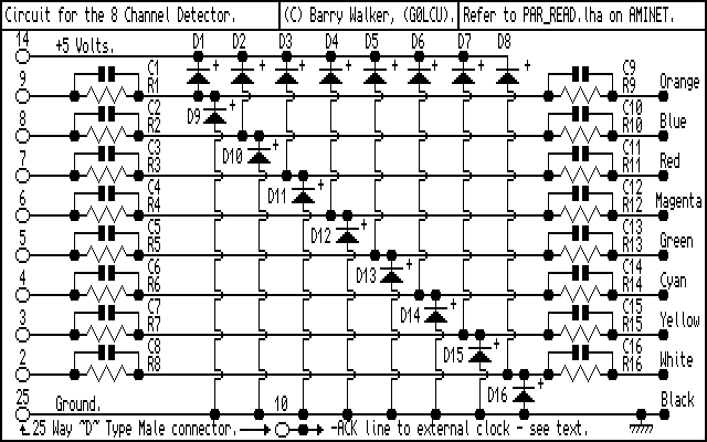
There is a confusing section in there as D1 to D7 are diodes - BUT - they are used as the data line INPUT names as well IN ALL OF THE TEXT SO FAR. Take care of this small amount of abiguity. Above for example D0 and GND refers to the earlier drawing ~DET_BRD1.GIF~ SO BE VERY AWARE!!!
There is no need to descirbe how it works as this was done in the last issue. It only needs a desription when C1 to C16 inclusive are fitted.
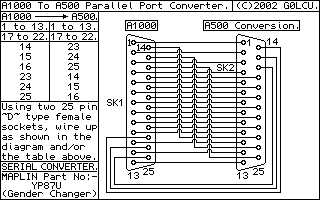
For use on an AMIGA A1000 a special converter cable is needed for the parallel port. Refer to the drawing 'A1000-Parallel-Adaptor.'where ??? = GIF or IFF. This changes the relevant lines from the A1000 specific layout to A500 and other classic AMIGAs compatibility.
When The 47pF Capacitors Are Fitted.
When the sixteen capacitors are fitted this board can be used as a LOGIC ANALYSER for up to about 200KHz sampling speed using a STOCK A1200(HD).
The capacitors are known as ~SPEED UP~ capacitors and are wired in parallel with the resistors to counteract any shunt capacitance that the wiring AND the diodes present.
I decided that the ~industry standard~ clock speed for a MIGGY to be 7MHz, the clock speed for the old A500. At this CPU clock speed, the reactance, (read impedance :), of each capacitor is approximately 470 Ohms, what a coincidence eh!... :)
This effectively helps to cancel out any sluggish rise and fall times of any logic lines being tested when this board is used as a LOGIC ANALYSER.
The final installment describes the three(+) methods of using the hardware using the default ARexx code, plus bwBASIC and Python, AND, how to modify the code to suit your needs. AmigaBASIC is included also AND use with an OLD STYLE A500 with OS1.3x, YEP that's right, it DOES work under Workbench 1.3x, (see the last issue :).
As AmigaBASIC is reasonably powerful, you could design your own simple GUI front end for this project and run it through Workbench 1.3x inside a Workbench window... :)
Last but not least, the last issue will include what is required for this to COLD BOOT, and auto-run, from floppy disk... :)
Good eh!... :)
These programs are Freeware and no profit will be made from them, also all of the files must remain unaltered and intact including this one. The author is not responsible for any damage to, or loss of, or failure of equipment or data caused in any way by the use of these programs. There is NO warranty with the use of these software releases and YOU USE THEM AT YOUR OWN RISK.
![]()
|
|