![]()
Sponsored by BoysStuff.co.uk
![]()
Sponsored by BoysStuff.co.uk

        Hardware Access Using The AmigaBASIC And ARexx Interpreters.
        ------------------------------------------------------------

                                   Part 5.
                                   -------

  Oh no, it's me again... :)

  Well we have successfully accessed pin 6 of the games port in BOTH modes.
  This article will describe writing to pin 6 of the games port to generate
  a PWM, (Pulse Width Modulation), serial DAC, (serial Digital to Analogue
  Converter).

  It generates a DC, (Direct Current), voltage in direct proportion to the
  M/S, (Mark to Space), ratio of a constant frequency pulse generator.

  Because there is no way to access inline machine code using ARexx then
  a version using the free 'ACE Basic Compiler' suite is included instead.
  There IS however an AmigaBASIC version which uses basic keyboard and
  mouse actions.

  There are two projects to view and one for a later date.

  1) A demonstation LED, (Light Emitting Diode), unit to prove it works.
  2) A very simple PWM to DC board that anyone can build in about an hour.
  3) A more sophisticated version of 2), for a later date.

  The demonstration LED unit ONLY will be described here in this article.

----------------------------------------------------------------------------

  Minimum Requirements:-
  ----------------------

  1) Standard A500, (the complete set).
  2) OS1.3x.
  3) TV.
  4) Default AmigaBASIC for the A500.
  5) Much disk swapping. (Do you remember that then eh!... :)

----------------------------------------------------------------------------

  The PWM LED Test Board.
  -----------------------

  This board demonstrates that the average voltage across the LED varies
  according to the M/S ratio of constant frequency square wave. It is NOT
  DC but an average of the M/S ratio. The brightness of the LED will alter
  giving an appearance of a variable DC voltage being applied across it.

----------------------------------------------------------------------------

  Tools:-
  -------

  The same as for all of the previous articles/projects.

  Specifications:-
  ----------------

  1) Cheap.
  2) Childishly easy to build.
  3) Is this, (are these), the only one(s) available!?!

----------------------------------------------------------------------------

  LED Board Circuit.
  ------------------


            +5V.
      Pin 7. O-----------------------+
                                     |
                                     |
                                   c * Q1
                                    /
                       R1       b |/
      Pin 6. O-------/\/\/\-----*-|
                                  |\
                                    \|
                                   e¯*
                                     |
                                     |
                                   .-+-.
                              LED1  \ / --->> (Green.)
AMIGA Games Port Pins.             --+--
----------------------               | +
                                      >
                                     <
                                      > R2
                                     <
                                      >
            GND.                     |
      Pin 8. O-----------*-----------+
                       __|__
                       /////

  Parts List.
  -----------

  1) R1 ..................................  1K, 1/4W, 10% tolerance.
  2) R2 ..................................  150 Ohms, 1/4W 10% tolerance.
  3) Q1 ..................................  Any small signal, high gain,
                                            silicon, NPN transistor.
                                            Examples:- BC108B, BC548B.
  4) LED1 ................................  Any small coloured LED, (green
                                            in the example board).
  5) Stripboard ..........................  10 holes by 4 tracks.
  6) 9 Pin ~D~ Type Socket ...............  Any solder bucket type.

  Notes:-
  -------

  1) All components obtained from any source.
  2) Tolerance + or - 10%.

----------------------------------------------------------------------------

  Construction, Refer To The Photographs And Drawings:-
  -----------------------------------------------------
 |
 |
 |
 |
(Click on the photos for a larger version)
1) Cut a piece of stripboard, 10 holes by 4 tracks in size.
2) Force one end between the pins of the 9 pin ~D~ type socket. The track
side to connect to four pin side of the socket, pins 6, 7, 8 and 9.
3) Solder into place.
4) Cut the tracks using a suitable small drill bit at the points shown
in the drawings and photographs.
5) Fit the 2 Resistors, Transistor and LED and solder into place.
IMPORTANT:- Note the orientation of the Transistor and LED!!!
6) Check your construction work...
7) Check it again!!! Check for short or open ciruits.
8) Check it a final time, REMEMBER any error may damage the computer.
9) You are now ready to roll.
10) Switch off the computer.
11) Plug the board into the Games Port
12) Switch on the computer and boot up into Workbench.
13) The LED should now be fully lit.
14) NOTE:- This board is safe enough to HOT plug into the computer if
built correctly without damaging the port.
----------------------------------------------------------------------------
Usage:-
-------
Until the archive is released to AMINET you will have to extract the code
inside this article and use it or compile it as required.
Also the 'tasking' and 'interrupts' are completely disabled whilst the
DAC is running, so be VERY aware if this, as the computer looks as though
it has locked up when in fact it hasn't. The AmigaBASIC Interpreter
version will be described here as this is one of the default programming
formats that these articles will relate to. The ACE Basic Compiler version
uses a simple GUI and mouse usage whereas the AmigaBASIC version has very
basic keyboard and mouse usage.
1) Switch OFF the computer.
2) Plug the LED test board into the games port.
3) Switch ON the computer and the LED should be fully lit up.
4) Boot up to at least the minimum requirements above.
5) Assuming that the absolute minimum requirements are being used be
prepared for lots of disk swapping... :)
6) Start AmigaBASIC and load in the 'PWM-LMB.bas' program into the
interpreter.
Download and see:-
http://main.aminet.net/dev/basic/AmigaBASIC-Info.lha
For usage on OS2.0x to OS3.1x.
7) Run the AmigaBASIC 'PWM-LMB.bas' program.
8) Follow the on screen prompts and watch the LED vary in brightness
according to the M/S ratio that you set the software to.
9) When finished testing, switch OFF the computer and remove the LED
board.
----------------------------------------------------------------------------
Enjoy experimenting and finding simple solutions to often difficult
problems. Now build the SIMPLE PWM to DC board below and test it in the
same way. This goes from about 0 to 2+ Volts DC in this form BUT is very
high impedance. It is for demonstration purposes only. There will be a
better design in another article on DACs and ADCs in the future...
----------------------------------------------------------------------------
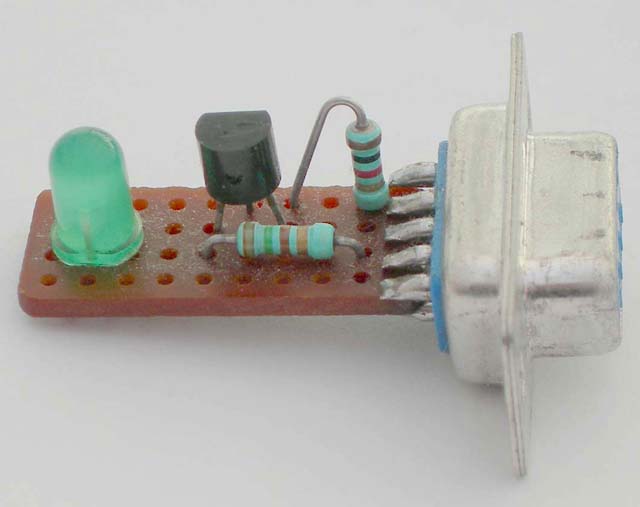
PWM To DC Circuit.
------------------
There are NO notes for the construction of this, only the photographs
and this circuit. You should be able build this now ready for the next
article on very simple Digital to Analogue AND Analogue to Digital
conversion using Pin 6 of the Games Port.
Note:- There is a flylead shown in the photographs; this is so that this
hardware can be used in another magazine issue to access Pin 9 of the
Games Port. I suggest you build it this way so as to save time in the
future.
 |
 |
(Click on the photos for a larger version)


         PWM IN.                                              DC OUT.
                      R1                 R2
      Pin 6. O------/\/\/\------*------/\/\/\------*------*------O +VE.
                                |                  |      |
                                |                  |       >
AMIGA Games Port Pins.          |                  |      <
----------------------      C1 ===             C2 ===      > R3
                                |                  |      <
                                |                  |       >
            GND.                |                  |      |
      Pin 8. O--------*---------*------------------*------*------O GND.
                    __|__
                    /////

  Parts List:-
  ------------

  1) R1 & R2 ......................  220K, 1/4W, 10% tolerance, any type.
  2) R3 ...........................  1M, 1/4W, 10% tolerance, any type.
  3) C1 & C2 ......................  0.1uF, any type, (50V or greater).
  4) Stripbord ....................  As required.
  5) 9 Pin ~D~ Type Socket.........  Any solder bucket type.

  Notes:-
  -------

  1) All components obtained from any source.
  2) Tolerance + or - 10%.
  3) Once built, to see this board working you will need either a very high
     impedance DC Voltmeter OR an Oscilloscope set to 0.5V/Div, DC mode
     connected across the +VE and GND outputs.
  4) The components for both of these circuits were obtained from my 'junk
     box' of salvaged bits off of old circuit boards.

----------------------------------------------------------------------------

  The Code Sections:-
  -------------------

  To use the code sections below, extract them from this article. They WILL
  be released complete with any executables, and, ARE released as of now,
  (this magazine issue date), under the GPL2 licence.

  Both the AmigaBASIC code and the ACE Basic Compiler code compiles as an
  executable under ACE Basic Compiler, (C)David Benn.

----------------------------------------------------------------------------

  AmigaBASIC Code PWM-LMB.bas:-
  -----------------------------

REM PWM Digital To Analogue Converter using AmigaBASIC.
REM Original idea copyright, (C)2007, B.Walker, G0LCU.
REM
REM Written for kids to understand.
REM
REM Use AmigaBASIC's default winodw.
REM This WILL compile under ACE Basic Compiler, (C)David Benn.

REM Set up an array for ~binary storage~.
  DIM code%(54)
  FOR n=1 TO 54
  READ code%(n)
  NEXT n
  GOTO begin:

REM Poke the machine code into memory.
  DATA &H48E7, &HFFFE, &H2C79, &H0000, &H0004, &H4EAE, &HFF7C, &H4EAE
  DATA &HFF88, &H203C, &H0000, &H0000, &H08F9, &H0007, &H00BF, &HE001
  DATA &H51C8, &HFFF6, &H0839, &H0006, &H00BF, &HE001, &H6602, &H601C
  DATA &H203C, &H0000, &H00FF, &H08B9, &H0007, &H00BF, &HE001, &H51C8
  DATA &HFFF6, &H0839, &H0006, &H00BF, &HE001, &H66C6, &H08B9, &H0007
  DATA &H00BF, &HE001, &H2C79, &H0000, &H0004, &H4EAE, &HFF82, &H4EAE
  DATA &HFF76, &H4CDF, &H7FFF, &H4280, &H4E75, &H4E71

REM Set up all variables.
begin:
  LET version$="$VER: PWM-LMB.bas_Version_0_10_00_(C)2007_B.Walker_G0LCU."
  LET a$="(C)2007 B.Walker G0LCU."
  LET peak$="0"
  LET peak=0
  LET trough=255
  LET n=0
  LET bitseven=0
  LET pwmaddr&=16777212&

REM Set up the games port, pin 6, for writing.
  POKE 12575233&,131

REM Point to the machine code routine.
  LET pwmaddr&=VARPTR(code%(1))
  GOTO setzero:

REM This is the user loop.
loopit:
  CLS
  COLOR 2,0
  LOCATE 2,10
  PRINT version$
  COLOR 1,0
  LOCATE 4,13
  PRINT "Pulse Width Modulated Digital To Analogue Converter."
  LOCATE 5,13
  PRINT "----------------------------------------------------"
  LOCATE 8,28
  PRINT a$
  LOCATE 10,6

  INPUT "Set output level; ~0~ minimum to ~255~ maximum, ~QUIT~ to quit:- ",peak$
  IF peak$="QUIT" OR peak$="EXIT" THEN GOTO getout:
  IF peak$="" THEN LET peak$="0"
REM Convert ANY string to a number and DO NOT ALLOW an error.
  LET peak=VAL(peak$)
  LET peak=INT(peak)
  IF peak<=0 THEN LET peak=0
  IF peak>=255 THEN LET peak=255
  IF peak=0 THEN GOTO setzero:
  IF peak=255 THEN GOTO setone:
  LET trough=255-peak

REM Poke into the machine code routine directly!!!
  POKE (pwmaddr&+23),peak
  POKE (pwmaddr&+53),trough

REM Print the mark to space values, IF ANY.
  LOCATE 8,28
  IF peak>=1 AND peak<=254 THEN PRINT "Mark =";peak;CHR$(8);", Space =";trough;CHR$(8);"."
  COLOR 3,0
  LOCATE 10,1
  PRINT "              Press the left mouse button to set a new value...              "

REM Call the machine code routine.
  CALL pwmaddr&

REM Set minimum directly and ALWAYS on the 'CALL' return.
setzero:
  LET bitseven=PEEK(12574721&)
  IF bitseven>=128 THEN POKE 12574721&,(bitseven-128)
  POKE (pwmaddr&+23),0
  POKE (pwmaddr&+53),255
  LET a$="Output set to minimum."
  GOTO loopit:

REM Set maximum directly.
setone:
  LET bitseven=PEEK(12574721&)
  IF bitseven<=127 THEN POKE 12574721&,(bitseven+128)
  POKE (pwmaddr&+23),255
  POKE (pwmaddr&+53),0
  LET a$="Output set to maximum."
  GOTO loopit:

REM Simple cleanup and exit.
getout:
REM Set the games port, pin 6 back to read.
  POKE 12575233&,3
  END

----------------------------------------------------------------------------

  Matching Assembler Code For The 'DATA' Inside AmigaBASIC Code:-
  ---------------------------------------------------------------

	;
	;PWM Generator For The Digital To Analogue Converter.
	;----------------------------------------------------
	;
	;$VER: PWM-LMB.asm_Version_0_10_00_(C)2007_B.Walker_G0LCU.
	;
	;Assembled using 'A68k'...
	;A68k -n PWM-LMB.asm[RETURN/ENTER]
	;
	;Linked using 'blink'...
	;blink PWM-LMB.o[RETURN/ENTER]
	;
start:					;START!!!
	movem.l	d0-d7/a0-a6,-(sp)	;Save all registers just in case!
					;
	movea.l	$4,a6			;Set the 'ExecBase' pointer.
	jsr	-132(a6)		;Offset -132 == [_LVO]Forbid()
					;Disable tasking and interrupts
	jsr	-120(a6)		;Offset -120 == [_LVO]Disable()
					;
					;
lmb:					;This is the PWM section.
	move.l	#127,d0			;Set the 'MARK' of the square wave.
markloop:				;
	bset	#7,$bfe001		;Set bit 7 of the games port.
	dbf	d0,markloop		;Do the timer for the 'MARK'.
	btst	#6,$bfe001		;Check to see if the left mouse
					;button is pressed.
	bne.s	delay			;IF NOT then continue.
	bra.s	cleanexit		;IF it is then quit.
delay:					;
	move.l	#128,d0			;Set the 'SPACE' of the square wave.
spaceloop:				;
	bclr	#7,$bfe001		;Reset bit 7 of the games port.
	dbf	d0,spaceloop		;Do the timer for the 'SPACE'.
	btst	#6,$bfe001		;Check to see if the left mouse
					;button is pressed to quit.
	bne.s	lmb			;IF NOT then loop until it is.
					;
cleanexit:				;
	bclr	#7,$bfe001		;Ensure output is set to zero.
	movea.l	$4,a6			;Set the 'ExecBase' pointer again.
					;NOTE:- This is a double check only!
	jsr	-126(a6)		;Offset -126 == [_LVO]Enable()
					;Enable interrupts and tasking.
	jsr	-138(a6)		;Offset -138 == [_LVO]Permit()
	movem.l	(sp)+,d0-d7/a0-a6	;Restore all registers.
					;
	clr.l	d0			;Ensure return code is 0.
					;
	rts				;Return to calling routine.
					;
	END				;END... SIMPLE EH!

  The HEX text from the compiled assembler above renamed to PWM-LMB.COM...
  From the CLI and the correct drawer type:-

  "Type HEX PWM-LMB.COM > PWM-LMB.HEX[RETURN/ENTER]" without the qoutes.

0000: 000003F3 00000000 00000001 00000000    ...ó............
0010: 00000000 0000001B 000003E9 0000001B    ...........é....
0020: 48E7FFFE 2C790000 00044EAE FF7C4EAE    Hç.þ,y....N®.|N®
0030: FF88203C 0000007F 08F90007 00BFE001    .. <.....ù...¿à.
0040: 51C8FFF6 08390006 00BFE001 6602601C    QÈ.ö.9...¿à.f.`.
0050: 203C0000 008008B9 000700BF E00151C8     <.....¹...¿à.QÈ
0060: FFF60839 000600BF E00166C6 08B90007    .ö.9...¿à.fÆ.¹..
0070: 00BFE001 2C790000 00044EAE FF824EAE    .¿à.,y....N®..N®
0080: FF764CDF 7FFF4280 4E754E71 000003F2    .vLß..B.NuNq...ò

  This is edited and then inserted into the DATA lines of the BASIC code.

----------------------------------------------------------------------------

  This very simple ARexx script is for the AmigaBASIC code above when
  compiled using ACE Basic Compiler to give PWM-LMB(.EXE).
  Note:- The '.EXE' extension is added after compilation of the AmigaBASIC
  code.

  ARexx Script PWM-LMB.rexx:-
  ---------------------------

/*                       THIS IS PUBLIC DOMAIN. */

/* A simple means of running the PWM program using AREXX. */
/* Ensure PWM-LMB.EXE is in the the same drawer as this ARexx script. */
/* A simple idea from B.Walker, G0LCU. */

ADDRESS COMMAND 'PWM-LMB.EXE'

ECHO 'a'x'a'x'                        Left click the close gadget.'

============================================================================

  ACE Basic Compiler Code PWM-RMB.b:-
  -----------------------------------

REM PWM Digital To Analogue Converter using ACE Basic Compiler.
REM ACE Basic Compiler, (C)David benn.
REM
REM Original idea copyright, (C)2007, B.Walker, G0LCU.
REM
REM Written for kids to understand.

REM Open up a standard Workbench window.
  WINDOW 1,"Pulse Width Modulator D-A Converter.",(0,0)-(640,200),6
  FONT "topaz.font",8
  COLOR 1,0
  CLS

REM Set up an array for ~binary storage~.
  DIM code%(54)
  FOR n=1 TO 54
  READ code%(n)
  NEXT n
  GOTO begin:

REM Machine code to be poked into memory.
  DATA &H48E7, &HFFFE, &H2C79, &H0000, &H0004, &H4EAE, &HFF7C, &H4EAE
  DATA &HFF88, &H203C, &H0000, &H0000, &H08F9, &H0007, &H00BF, &HE001
  DATA &H51C8, &HFFF6, &H0839, &H0002, &H00DF, &HF016, &H6602, &H601C
  DATA &H203C, &H0000, &H00FF, &H08B9, &H0007, &H00BF, &HE001, &H51C8
  DATA &HFFF6, &H0839, &H0002, &H00DF, &HF016, &H66C6, &H08B9, &H0007
  DATA &H00BF, &HE001, &H2C79, &H0000, &H0004, &H4EAE, &HFF82, &H4EAE
  DATA &HFF76, &H4CDF, &H7FFF, &H4280, &H4E75, &H4E71

REM Set up ALL variables.
begin:
  LET version$="$VER: PWM-RMB_Version_0_20_00_(C)2007_B.Walker_G0LCU."
  LET thegadget=255
  LET peak=0
  LET trough=255
  LET n=0
  LET bitseven=0
  LET pwmaddr&=16777212&

REM Set pin 6 of the games port to WRITE mode.
  POKE 12575233&,131

REM Point to the machine code routine.
  LET pwmaddr&=VARPTR(code%(1))

REM Set up a slider and fixed 'QUIT' gadget(s).
  GADGET 255,1,255,(28,70)-(595,80),4,0
  GADGET 254,1,"Quit.",(274,93)-(344,109),BUTTON,1,"topaz.font",8,0
REM Set up a fake MENU.
  MENU 1,0,1,"(C)2007, G0LCU."
  MENU 1,1,1,"Barry Walker."

REM This is the startup screen and user loop.
  COLOR 0,0
  LOCATE 2,12
  PRINT version$
  COLOR 1,0
  LOCATE 4,13
  PRINT "Pulse Width Modulated Digital To Analogue Converter."
  LOCATE 5,13
  PRINT "----------------------------------------------------"
  LOCATE 8,28
  PRINT "(C)2007 B.Walker G0LCU."
  LOCATE 10,3
  PRINT "0"
  LOCATE 10,76
  PRINT "255"
  SLEEP FOR 1
  GOTO setzero:

REM Wait for a gadget event.
loopit:
  GADGET WAIT 0
  LET thegadget=GADGET(1)
  IF thegadget=255 THEN LET peak=GADGET(3)
  IF thegadget=254 THEN GOTO getout:

REM Poke into the machine code routine directly!!!
  LET trough=255-peak
  POKE (pwmaddr&+23),peak
  POKE (pwmaddr&+53),trough
  LET peak=PEEK(pwmaddr&+23)
  IF peak=0 THEN GOTO setzero:
  IF peak=255 THEN GOTO setone:

REM Print the mark to space values, IF ANY.
  LOCATE 8,28
  IF peak>=1 AND peak<=254 THEN PRINT "Mark =";peak;CHR$(8);", Space =";trough;CHR$(8);".        "

REM Print a help line.
  COLOR 1,0
  LOCATE 16,15
  PRINT "Press the ";
  COLOR 2,0
  PRINT "RIGHT";
  COLOR 1,0
  PRINT " mouse button to set a new value!"

REM Call the machine code routine.
REM The RMB MUST be pressed to exit the 'CALL' routine!!!
  CALL pwmaddr&

REM Clear the help line.
  COLOR 1,0
  LOCATE 16,15
  PRINT "                                                 "

REM Deliberately set the output to minimum on 'CALL' exit.
setzero:
  LET bitseven=PEEK(12574721&)
  IF bitseven>=128 THEN POKE 12574721&,(bitseven-128)
  POKE (pwmaddr&+23),0
  POKE (pwmaddr&+53),255
  LOCATE 8,28
  PRINT "Output set to minimum.        "
  GOTO loopit:

REM Set maximum directly.
setone:
  LET bitseven=PEEK(12574721&)
  IF bitseven<=127 THEN POKE 12574721&,(bitseven+128)
  POKE (pwmaddr&+23),255
  POKE (pwmaddr&+53),0
  LOCATE 8,28
  PRINT "Output set to maximum.       "
holdmax:
  IF MOUSE(0)=0 THEN GOTO holdmax:
  GOTO setzero:

REM Simple cleanup and exit.
getout:
REM Clear the menus.
  MENU CLEAR
REM Close the gadgets.
  GADGET CLOSE 254
  GADGET CLOSE 255
REM Set pin 6 of the games port back to READ mode.
  POKE 12575233&,3
REM Close down the window.
  WINDOW CLOSE 1
  END

  Note:- The '.EXE' extension is added after compilation of the above code.

----------------------------------------------------------------------------

  Matching Assembler Code For The 'DATA' Inside ACE Basic Compiler Code:-
  -----------------------------------------------------------------------

	;
	;PWM Generator For The Digital To Analogue Converter.
	;----------------------------------------------------
	;
	;$VER: PWM-RMB.asm_Version_0_10_00_(C)2007_B.Walker_G0LCU.
	;
	;Assembled using 'A68k'...
	;A68k -n PWM-RMB.asm[RETURN/ENTER]
	;
	;Linked using 'blink'...
	;blink PWM-RMB.o[RETURN/ENTER]
	;
start:					;START!!!
	movem.l	d0-d7/a0-a6,-(sp)	;Save all registers just in case!
					;
	movea.l	$4,a6			;Set the 'ExecBase' pointer.
	jsr	-132(a6)		;Offset -132 == [_LVO]Forbid()
					;Disable tasking and interrupts
	jsr	-120(a6)		;Offset -120 == [_LVO]Disable()
					;
					;
rmb:					;This is the PWM section.
	move.l	#127,d0			;Set the 'MARK' of the square wave.
markloop:				;
	bset	#7,$bfe001		;Set bit 7 of the games port.
	dbf	d0,markloop		;Do the timer for the 'MARK'.
	btst	#2,$dff016		;Check to see if the right mouse
					;button is pressed.
	bne.s	delay			;IF NOT then continue.
	bra.s	cleanexit		;IF it is then quit.
delay:					;
	move.l	#128,d0			;Set the 'SPACE' of the square wave.
spaceloop:				;
	bclr	#7,$bfe001		;Reset bit 7 of the games port.
	dbf	d0,spaceloop		;Do the timer for the 'SPACE'.
	btst	#2,$dff016		;Check to see if the right mouse
					;button is pressed to quit.
	bne.s	rmb			;IF NOT then loop until it is.
					;
cleanexit:				;
	bclr	#7,$bfe001		;Ensure output is set to zero.
	movea.l	$4,a6			;Set the 'ExecBase' pointer again.
					;NOTE:- This is a double check only!
	jsr	-126(a6)		;Offset -126 == [_LVO]Enable()
					;Enable interrupts and tasking.
	jsr	-138(a6)		;Offset -138 == [_LVO]Permit()
	movem.l	(sp)+,d0-d7/a0-a6	;Restore all registers.
					;
	clr.l	d0			;Ensure return code is 0.
					;
	rts				;Return to calling routine.
					;
	END				;END... SIMPLE EH!

  The HEX text from the compiled assembler above renamed to PWM-RMB.COM...
  From the CLI and the correct drawer type:-

  "Type HEX PWM-RMB.COM > PWM-RMB.HEX[RETURN/ENTER]" without the qoutes.

0000: 000003F3 00000000 00000001 00000000    ...ó............
0010: 00000000 0000001B 000003E9 0000001B    ...........é....
0020: 48E7FFFE 2C790000 00044EAE FF7C4EAE    Hç.þ,y....N®.|N®
0030: FF88203C 0000007F 08F90007 00BFE001    .. <.....ù...¿à.
0040: 51C8FFF6 08390002 00DFF016 6602601C    QÈ.ö.9...ßð.f.`.
0050: 203C0000 008008B9 000700BF E00151C8     <.....¹...¿à.QÈ
0060: FFF60839 000200DF F01666C6 08B90007    .ö.9...ßð.fÆ.¹..
0070: 00BFE001 2C790000 00044EAE FF824EAE    .¿à.,y....N®..N®
0080: FF764CDF 7FFF4280 4E754E71 000003F2    .vLß..B.NuNq...ò

  This is edited and then inserted into the DATA lines of the BASIC code.

  NOTE:- ACE Basic Compiler CAN easily cater for the inline assembler
  coding directly, using the ASSEM and END ASSEM statements but was ignored
  for this experiment.

----------------------------------------------------------------------------

  This very simple ARexx script is for the ACE Basic code above when
  compiled using ACE Basic Compiler to give PWM-RMB(.EXE).
  Note:- The '.EXE' extension is added after compilation of the ACE Basic
  code.

  ARexx Script PWM-RMB.rexx:-
  ---------------------------

/*                       THIS IS PUBLIC DOMAIN. */

/* A simple means of running the PWM program using AREXX. */
/* Ensure PWM-RMB.EXE is in the the same drawer as this ARexx script. */
/* A simple idea from B.Walker, G0LCU. */

ADDRESS COMMAND 'PWM-RMB.EXE'

ECHO 'a'x'a'x'                        Left click the close gadget.'

----------------------------------------------------------------------------

  Last but not least, to see how I set about using Pin 6 of the Games Port
  as a 10MHz Frequency Counter download the file......

                http://main.aminet.net/docs/hard/TestGear5.lha

  ......Project14 and the ACE Basic Compiler source code is in the archive.

  Enjoy finding simple solutions to often, very difficult problems... :-)

  The next part will access Pin 9, (and/or 5), of the Games Port in DIGITAL,
  the DEFAULT, read mode. ANALOGUE read mode will follow at a later date.

============================================================================

                                IMPORTANT:-
                                -----------


    The Legal Stuff:-
    -----------------

    These programs are Freeware and no profit will be made from them,
    also all of the files must remain unaltered and intact including this
    one. The author is not responsible for any damage to, or loss of, or
    failure of equipment or data caused in any way by the use of these
    programs. There is NO warranty with the use of these software releases
    and YOU USE THEM AT YOUR OWN RISK.

----------------------------------------------------------------------------

    Testing Evaluation:-
    --------------------

    An A1200(HD) in 2MB, 6MB and 10MB modes using trapdoor memory AND/OR
    PCMCIA memory expansions. Also tested on an A600(HD) in 2MB and 6MB
    modes. All test conditions were/are running STANDARD KS2.0x to 3.1x,
    and using standard ~topaz 8~ fonts throughout.

    I have no idea what a strange configuration setup will create so refer
    to the ~The Legal Stuff~ above.

----------------------------------------------------------------------------

                                 WARNING.
                                 --------

  1) DISCONNECT any faulty equipment under test from the MAINS supply.
  2) If a DC supply is used do NOT reverse polarity the connections.
  3) Do NOT power up any electronic item until it is safe to do so.
  4) CHECK and RECHECK all of your construction and repair work thoroughly.
  5) Handle ALL tools used with care.
  6) Beware of ALL types of solvents, glues and etching fluids.
  7) NEVER leave a soldering iron switched on unattended.
  8) KEEP everything OUT of the reach of small children.
  9) Switch OFF the AMIGA before disconnecting or connecting any hardware.
 10) And finally read 1) to 9) again.

----------------------------------------------------------------------------

   Contact:-
   ---------

   Mr Barry Walker, G0LCU.

   Email:-     wisecracker@tesco.net
   URL:-       http://homepages.tesco.net/wisecracker/G0LCU.HTM

   Author of the ~TestGear?~ projects in the ~docs/hard~ drawer of AMINET.

----------------------------------------------------------------------------

   A very useful HardWare related site, (C) Anthony Hoffman, for
   modifications, schematics, repairs and the like is:-

                          http://amiga.serveftp.net/

============================================================================
![]()
| © RIYAN Productions |

|